Guides / Processes
Thread Gauging for Custom Fasteners: 6g, 2A and System 22
October 21, 2026
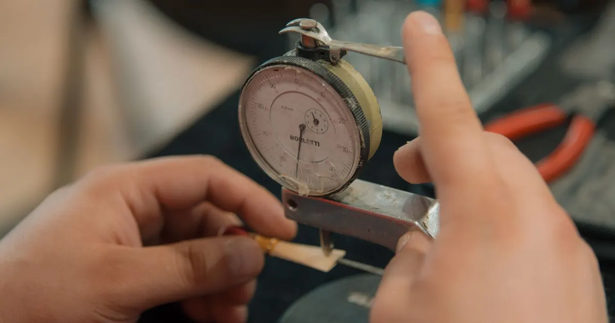
A thread is a three dimensional helix, and no single caliper measurement shows if it will assemble. Gauging solves that with fixed steel gauges that act like the mating nut or bolt. A plant checks a sample from every lot, and a buyer who understands the system can state the requirement in one line on the print. This guide explains what the codes mean, how the gauges work and what to write.
What 6g and 2A mean
Standards describe threads by a tolerance class. The two most common in fasteners are these.
Metric: ISO 965-1. An external thread is written as M10 x 1.5 6g. The pitch is 1.5 mm. The class 6g has two parts. The 6 is the tolerance grade for the pitch diameter and the major diameter, a medium width. The g is the tolerance position: a small allowance, which means the thread is made slightly below the basic size. Nuts use capital letters, with 6H the common class for internal threads. A 6g bolt in a 6H nut gives a clearance fit with room for a thin coating on the bolt. The position h has zero allowance and is tighter. Grade 4 gives a narrower tolerance than 6.
Inch: ASME B1.1. A unified thread is written 1/2-13 UNC-2A. The 13 is threads per inch, UNC is coarse and 2A is the class for external threads, with 2B for internal. Class 2A has an allowance for coating and fits like 6g does in metric. Class 3A has no allowance and a smaller tolerance, used where the fit must be tight. Class 1A is looser and rare.
| System | Class | Allowance | Typical use |
|---|---|---|---|
| ISO 965-1 | 6g | Small, for coating | General external threads |
| ISO 965-1 | 6h | None | Closer fit, or after coating |
| ISO 965-1 | 4h | None, narrower tolerance | Precision parts |
| ASME B1.1 | 2A | Small, for coating | General external threads |
| ASME B1.1 | 3A | None, narrower tolerance | Close fit, precision parts |
These are the typical choices. A print should always state the class.
How go and no-go gauges work
A thread gauge has two ends for a ring or a plug.
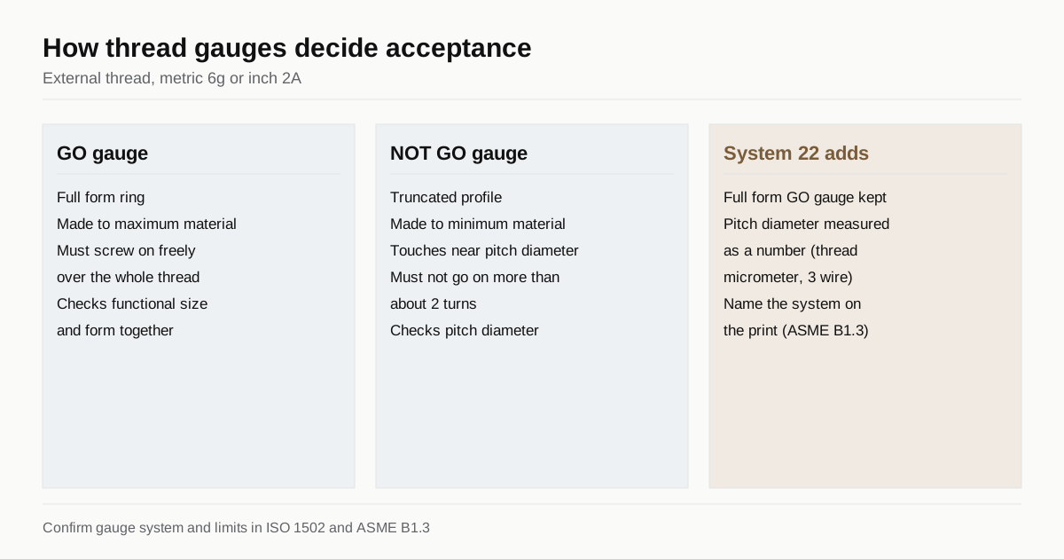
GO gauge. It is a full form ring, for external threads, or a plug, for internal ones, made to the maximum material limit. It has the complete thread profile. When the gauge turns freely onto the whole thread length, it proves that the pitch diameter is not too large, and that lead, flank angle and form do not combine to bind. It checks the functional size, which is the diameter of the thread that a mating part feels.
NOT GO gauge. It is also called HI. It has a truncated profile that touches only the flanks near the pitch diameter, and it is made to the minimum material limit. A thread passes when this gauge does not screw on more than about two turns. It checks that the pitch diameter is not too small. ISO 1502 sets the gauge system for metric threads.
For a nut, the same pair is made as plugs. For a bolt, ring gauges are common, though a snap gauge with rolls can check a thread faster on a production line. Gauges are made to their own tolerance and are checked against setting plugs, because they wear.
Gauging does not tell you the thread’s true pitch diameter. It tells you if the thread is within limits. For more, a plant measures with thread micrometers, a three wire method or an optical comparator.
What System 22 adds
ASME B1.3 defines acceptability systems for unified inch threads. A system is a set of rules for which gauges and which measurements decide if a thread is acceptable. Systems 21, 22 and 23 are the ones you will see on drawings.
- System 21 relies on fixed attribute gauges: a full form GO gauge for functional size and a NOT GO gauge for pitch diameter, plus gauges for major and minor diameters where needed.
- System 22 keeps a full form GO gauge and adds a measured pitch diameter value, taken with variable gauges such as a thread micrometer or a gauge with indicator.
- System 23 adds further measurement requirements for more critical product.
The reason to call out a system on a print is that the same thread can pass one and fail another. A thread that passes a NOT GO gauge may have a measured pitch diameter that sits near the limit, and a measured check shows it. Check the exact content of each system in ASME B1.3 before you cite it, and name the system plainly on the drawing, for example “gauge to ASME B1.3 System 22”.
Coating and gauging
Coating adds material to the thread, so the point at which you gauge matters. There are two common approaches.
- Gauge after coating. The finished thread must pass the GO gauge at its class limit. The allowance in 6g or 2A absorbs a thin coat. A thick coat needs a pre-coating thread made smaller, and the plant must know the coating thickness to set it.
- Gauge before coating, with a stated allowance. The thread is checked at the final tolerance before it goes to the coater, and the coater controls the thickness.
Both work if the print says which applies. Without a statement, the plant picks the cheapest and you may find out at assembly. A thread rolled before heat treatment can also change in size slightly in the furnace, so a plant that gauges after treatment is checking the finished state. See thread rolling vs cutting for how the process affects the thread.
Typical gauging in a custom order
| Stage | Typical check |
|---|---|
| First article | Full dimensional report, GO and NOT GO on every thread, pitch diameter measured |
| In process | GO gauge at set intervals during the run |
| Final lot inspection | Sample per ISO 3269 or the agreed plan, GO and NOT GO |
| Coated parts | GO gauge after coating, coating thickness check |
Sample size and frequency depend on the agreed plan. For critical parts, ask for 100 percent GO gauging, which is cheap compared with the cost of a failed assembly line. Also ask for a record of the gauge calibration date, since a worn gauge accepts bad parts.
Where gauging problems start
Most disputes over thread fit come from the print, not the plant. The usual causes are:
- The class is missing, so the plant uses its default.
- The print says M12 with no pitch, and the plant guesses coarse.
- Coating is on the print but no gauging point is stated.
- The thread runs to a shoulder, so the GO gauge cannot reach the end.
- The thread length is shown as a minimum with no gauging rule.
A complete thread callout avoids all five. Combine it with an inspection note, and the maker can quote the right gauge set and the right cost. The RFQ checklist for custom fasteners lists the other items to include on the first message.
Examples of how a callout changes the gauge set
M8 x 1.25 6g, plain steel, no coating. The plant needs a GO ring and a NOT GO ring for M8 x 1.25 6g, plus a calibrated setting plug for each. The checks are quick and cheap, and nearly every plant stocks them for standard sizes.
1/4-28 UNF-2A with zinc plating. The plant gauges after plating, so the thread is made near the lower end of the class before it goes to the coater. If the print also says System 22, the plant adds a measured pitch diameter, which needs a thread micrometer or a three wire setup and a record for each sample. This takes longer per part and shows in the inspection charge.
A non-standard thread, 9/16-24 with a special length. Gauges for odd sizes may not exist off the shelf. The plant either buys custom gauges, which takes weeks and a cost, or measures with optical methods. Ask early, because gauge lead time can set the schedule for a first article.
Gauge care and calibration
A gauge is a precision part that wears each time it is used, and a worn GO ring accepts a thread that is slightly too large. A plant should keep gauges in a controlled place, check them against setting plugs at set intervals and retire them when they wear to the wear limit. Gauges have a stated wear limit, and the standards for them describe how tolerance is split between the gauge and the part.
You can ask three simple questions. Which gauges does the plant use for this thread and are they in calibration? How often does the plant check gauges against masters? Does the inspection record show the gauge identity for each lot? A plant that answers quickly has a system. A plant that cannot answer may still make good parts, but you have less evidence.
Checklist for the print
- Thread size, pitch and class, for example M10 x 1.5 6g or 1/2-13 UNC-2A.
- Gauging system or standard, such as ISO 1502 or ASME B1.3 System 22.
- Whether threads are gauged before or after coating.
- Thread length and the runout rule.
- Sampling rule or a request for 100 percent GO gauging.
Add these and the quotes will reflect the real inspection effort. When the print is complete, send your RFQ and we will pass it to up to three makers that can gauge to your system.
See also the reference page on ISO metric threads, with pitches, stress areas and tolerance positions.
Frequently asked questions
What does 6g mean on a metric thread?
It is a tolerance class from ISO 965-1. The number 6 is the tolerance grade, which sets how wide the tolerance band is. The letter g is the position: a small negative allowance below the basic size, which leaves room for a thin coating. It is the default class for general purpose external metric threads.
Is a go and no-go ring gauge enough to accept a thread?
For most commercial work yes. The go ring checks that the thread assembles and has enough material on every element. The no-go ring checks that the pitch diameter is not too small. Critical parts may add measured pitch diameter, major diameter and lead checks.
Do I gauge before or after coating?
Say it on the print. A common practice is that the thread must meet its limits after coating, and a 6g or 2A thread has a small allowance for that. If the coating is thick, the thread needs to be made smaller before coating, and the plant needs to know the coating thickness to do that.
Need this fastener made?
Send the print with the grade and annual volume. We match you with up to 3 makers that run the right route and reply within 24 business hours.
Send my RFQ